Category
- Products
- FAQ
- Contact us

Frequency inverter manufacturers
Home » Application » Frequency inverter for HVAC system
Frequency inverter for HVAC system
The AC power available to us needs to be controlled and transformed so as to effectively meet the requirement of any application while realizing the desired output. IEEE (Institute of Electrical and Electronic Engineers) estimates that more than 90% of such requirements are met by using AC motors and the vast majority of these are three phase induction motors.
These motors are essentially constant speed motors and lack any provisions for speed control when running on main power and are intrinsically unable to adjust to the changing load demands of the application. Therefore suitable external equipment has to be used to control their speed.
Frequency inverter makes it possible to match the speed of the motor to the load or process requirement which also ensures avoidance of losses which may otherwise occur by using other conventional methods.
Again by IEEE estimates 60% - 65% of process needs met by induction motors are for centrifugal fans, pumps and compressors. All these loads are governed by processes, which demand variation of flow and conventional methods to achieve the same are through:
By using an inverter, a stepless control of motor speed in tune with load requirements encountered by fans or pumps is possible. Retrofitting these frequency inverters onto existing installations can be easily done and therefore a very viable proposition exists of making existing installations of fans and pumps more energy efficient.
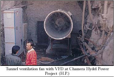
The Basics
It is worthwhile for HVAC engineers to understand some basic definitions and issues concerning frequency inverters before applying them on fans and pumps in their system design or in existing installations.
1. Definition – inverter
Inverters are devices used for varying the speed of a driven equipment (such as pumps, blowers, conveyors, extruders, etc) to exactly match the process requirements and achieve energy savings as well, especially for variable torque loads.
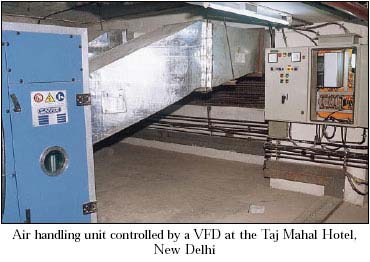
2. Frequency inverters
While strictly by definition a "inverter" can be any device which controls the speed of a "driven equipment" the focus of discussion in this article will be restricted to an electronic controller which controls the speed of the induction motor.
A frequency inverter is a device which consists of a frequency converter that can vary the frequency and voltage of the supply fed to the induction motor. The speed of the most commonly used industrial motor, the squirrel cage induction motor, can be varied by varying the frequency of the power supply. frequency inverters facilitate energy savings by variable speed operation, that will be discussed in greater detail later.
3. Concept of Electronic inverters
Any electronic inverter system comprises of the following three components:

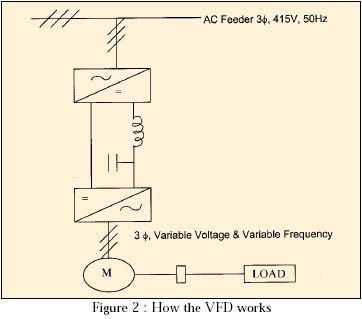
A frequency inverter consists of an input rectifier (which converts AC to DC) followed by an inverter (that inverts DC to AC) connected through a DC intermediate voltage link. The basic line schematic is shown in Figure 2. For simplicity we are only considering three phase systems though single phase systems are also available within a restricted power range.
Every standard AC motor can be fitted with a frequency inverter for variation of mains supply frequency in line with speed variations required. Both frequency and voltage of single phase or three phase mains are varied by the frequency inverter so as to ensure that the motor can be operated with varying speeds over large range settings.
4. Loading Patterns
All driven equipment has a load characteristic or a speed and torque relationship which can be broadly classified as follows:
Constant Torque loads are those for which the output power requirement may vary with speed of operation but the torque does not vary. Conveyors, extruders, rotary kilns, positive displacement pumps are typical examples of CT loads.
Variable Torque Load (VT)
Variable Torque loads are those for which the torque required varies with the speed of operation. Centrifugal pumps and fans are typical examples of VT loads (torque varies as the square of speed) Our main topic of discussion will revolve around VT loads only as the largest potential for energy savings exists for this loading pattern in which as the speed is varied the power requirement changes as the cube of the speed.
Constant HP/Power Load
Constant HP / Power loads are those for which torque requirement typically change inversely with speed. Winders and coilers are typical examples of constant power loads.
5. Speed Control of AC Motor
In an AC induction motor due to the tendency of the rotor magnetic field to be aligned with the stator field, the rotor develops the torque in the same direction and it starts rotating. The speed of the rotor however is less than the synchronous speed (NS) – the speed of the rotating magnetic field developed by the stator.

Hence the speed of an AC motor is a function of frequency and the number of motor poles.
The difference between the synchronous speed (Ns) and the actual rotor speed (N) is called the Slip (s). If there is no slip there will be no rotor current and torque, as induced emf into the rotor will be zero.
The speed of an induction motor is directly proportional to the supply frequency. By gradually changing the supply frequency, speed can be increased or decreased continuously and precisely.
If speed control is to be achieved by changing frequency, the supply voltage also has to be changed simultaneously. This is because if frequency (f) is reduced keeping the supplied voltage (V) constant, flux is increased, which causes increase in excitation current and larger losses and thus affects the efficiency of the motor.
On the other hand if the frequency (f) is increased with applied voltage (V) constant, flux will decrease thereby reducing torque.
Therefore it is important that the frequency and voltage should be changed proportionately. The constant V/f ratio of frequency inverters work on this principle.
The electronic frequency inverter can be used to vary the speed of an AC motor and at the same time retain its torque producing capability. The main power source provides a fixed voltage, fixed frequency supply that is converted into a variable voltage, variable frequency output in such a way that in most of the operating speed range, the V/f ratio is maintained constant. This of course is achieved though sophisticated microprocessor based control electronics.
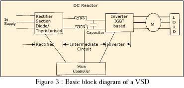
The principle involved in this technique is first to convert the fixed frequency, fixed voltage AC supply into a constant DC voltage through rectification. This DC voltage is then inverted into a variable frequency, variable voltage AC supply at the desired level as determined by the reference level and controlled by the main controller.
It is recommended that a DC reactor be installed at both limbs in the intermediate circuit level for controlling harmonics. See Figure 3.
In an effort to reduce operating expenses, the one most commonly replaced piece of equipment in an existing central air conditioning plant in an old building, is the packaged chiller (or chillers) either reciprocating or centrifugal, because most operating engineers know that the old chillers, before the energy crisis of the 1970s, were quite inefficient or because of their experience with frequent breakdowns in the past and / or difficulty in obtaining spare parts.
What many engineers do not realize is the potential for very large additional energy savings possible in old buildings by using frequency inverters to reduce the speed of fans in air handling units or the secondary chilled water pumps, in line with the reduction in heat load from morning to evening hours and from season to season as the outdoor temperature varies or as the internal load of equipment and occupants is reduced.
Fans and pumps in such buildings run at full speed all the time, which is wasteful. If control valves are installed in the chilled water lines to each air-conditioning unit or bypass dampers are installed across the cooling coils and controlled through a space thermostat (which is rarely the case in old buildings in India) this method of control of cooling capacity is inefficient and wasteful. Of the total power consumed by a typical office building, a central air conditioning plant alone consumes approximately 60%.
Affinity Laws governing fluid flow
The characteristics of centrifugal equipment such as blowers and pumps versus flow can be explained by the following basic equations:
Energy Savings through Speed Control
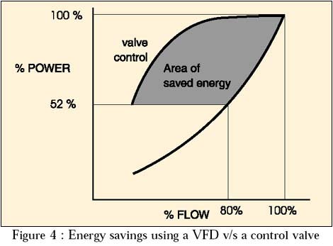
The power consumption of a blower or pump therefore follows the "Cube Law", which means that by reducing the speed to 80% of the maximum value the power consumption will be reduced to about 50%. As an example, at 80% speed the power consumption is (0.8)3 or 0.512 or 51.2% Variable air systems using constant speed fans with dampers or inlet guide vanes controlling the airflow consume a lot of energy by constantly running the motor at full speed. Similarly in chilled water circuits with both chillers and pumps running at constant speed, energy is wasted by using by-pass loops returning the excess chilled water not required by the plant for the reduced heat load at that point of time. Energy saving of upto 50% or more is often possible in a typical installation after using a frequency inverter. Figure 4 shows the typical power consumption using "valve control" and "frequency inverter" control in a chilled water loop.
The actual savings will of course depend on the variations in cooling load, since on very warm days the air conditioning and ventilation systems will have to run at full speed but such situations occur on very few occasions in a year or may be a couple of hours in a day. The rest of the year or during off-peak periods each day there is scope for energy saving. To more accurately estimate such savings it is necessary to take each chilled water pump and fan system and work out the number of hours the pump or fan has to work at a particular speed (or flow requirement based on the cooling load) during a 24 hour cycle which will help to draw a load or energy consumption profile. Multiplying the number of running hours at various speeds (h) by the associated amount of power (kW) from Table 1 and adding the values will show the total energy consumption (kWh) per year, of the pump or fan motor controlled by the frequency inverter.
Compared to constant speed operation the difference from the above variable speed calculations represents the savings in energy. By repeating this calculation for other pump and fan systems within a building, the total energy saving of the whole building can be worked out.
Figure 5 shows a typical capacity characteristic of a pump as well as the associated motor shaft output in kW Figures may vary a little bit from manufacturer to manufacturer based on the design adopted.
By using an automatic water valve to control flow from AI to BI follow the solid curve in the lower part of Figure 5 to work out the power saving.
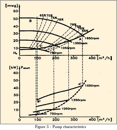
By speed regulation it is possible to utilize the pump characteristic and hence power consumption follows the dotted curve from AI to CI.
A theoretical example based on general experience as well as a practical example, will illustrate how power savings can be calculated.
Example 1
A 15kW AHU operating for 12 hours during weekdays and 6 hours during week ends. In total 66 hours per week.
a. Energy cost at constant speed
Energy consumption per week: 15kW × 66h = 990 kWh.
Assume electricity rate is $5.00 per kWh
Energy cost per year: 990 kWh ´× $5.00 × 52 weeks = $2,57,400
b. Energy cost at variable speed
Assume average speed is 75% corresponding to 42% power consumption.
Energy consumption per week: 0.42 × 15kW × 66h = 416 kWh
Energy cost per year: 416 kWh × $5.00 X 52 = $1,08,160
c. Value of energy saved by using "frequency inverter"
$2,57,400 – $1,08,160 = $1,49,240
d. Investment for running a frequency inverter
(approximate figures)
Application engineering
frequency inverter price
Differential pressure transmitter
Installation, commissioning, cabling etc.
=$1,80,000
e. From the above one can see that the payback period is typically 1.20 years.
Notes:
Example 2
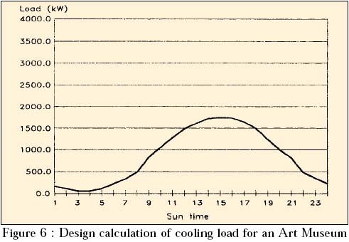
We can now take a real life example where the building's cooling curve is used to prepare the speed profile of the motor. See Figures 6 and 7.
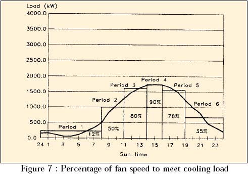
Based on Figure 6, a block cooling load profile was made giving some expected average fan speed requirement values in percentages using frequency inverter's to meet the cooling load.
From Good Practice Guide issued by the UK Department of Energy, graphs were used to convert the fan speed percentage given in Figure 7 to power consumption percentage, given in Table 1.
Variable Speed Duty
Based on average fan speeds as noted in Figure 7 and the per cent power consumption from Good Practice Guide, the energy consumption in the different periods as well as the total energy consumption (kWh) for variable speed duty can be calculated and summarized as in Table 1.
Table 1 : Summary of energy consumption for variable speed duty based on Figure 7 and 'Good Practise Guide' issued by the U.K. Dept. of Energy
For the alternative, constant speed duty calculations of the energy consumption were also made.
Constant Speed Duty (Average Values)
To arrive at a reasonable figure of average load for constant speed duty, we assume the following:
1. Reduction in mechanical wear and tear
When a HVAC installation no longer runs at full speed additional benefits apart from those related to energy savings are available:
As a byproduct of the energy savings from reducing fan speeds, acoustic air movement noise from the fan is also reduced.
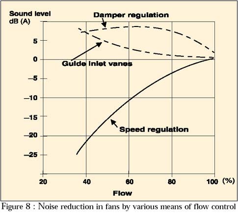
Noise from fans in a quiet environment can be very annoying. If a fan sized for full occupancy is supplying a partly occupied room, the acoustic noise level can be as high as 70 dbA. The noise level will vary depending on the throttling with dampers or guide vanes. More the throttling, greater is the noise.
Keeping dampers or guide vanes fully open and reducing the speed from 100% to say 50% reduces the noise by 16.5 dbA. (A reduction of 10 dbA corresponds to a 50% reduction in the noise level)
The following formula shows how to calculate the above:

The relationship is graphically shown in Figure 8.
3. Drafts
By reducing the speed of a centrifugal fan the draft from a fan system can be very much reduced. This also increases comfort.
4. Leaks
Leaking water from pump systems, usually caused by water hammer can be totally avoided by using a frequency inverter with zero starting surge. This also extends the life time of pipe work and fittings.
5. Controlling comfort
When using a frequency inverter instead of an inlet guide vane or damper, accurate temperature and pressure control can be maintained as the response time of a frequency inverter to a BMS (building management system) correction signal is very fast and smooth.
Calculations of Payback Time
When calculating energy savings it is important to have the information required to obtain the expected energy savings. And most interesting of all, work out the pay back time of the investment.
Calculation of the pay back time is initially done for each frequency inverter installed and eventually the data for other frequency converters is added. But before anything else it is important to mention that a substantial amount of application engineering must be done to realize the expected energy savings. For example the position of the sensor is very important for obtaining the "cubic savings" which calls for a thorough understanding of the application.
If the sensor is not positioned properly in the duct work not only will "cubic savings" not be obtained but the linear savings actually obtained will be at a lower efficiency and the overall system may not save much, if at all.
Firstly the investment necessary for obtaining energy savings has to be calculated:
Thirdly, the savings on maintenance has to be added to establish the total savings. Eventually the pay back time can be calculated as the total cost of having a frequency inverter installed divided by the total savings (energy and maintenance) for one year.
Pay back time (simple)
Total cost of installing frequency inverter / Total energy savings for one year.
Pay back time(real)
Total cost of installing frequency inverter / Total energy savings per year + savings on maintenance and spare parts.
Government Incentives
Many governments including that of India are actively considering a special depreciation scheme towards investments made in energy saving equipment. CII is actively propagating this concept with the government to encourage control/reduction of energy demands in the country as energy saved means more energy available at a much lower cost. The Singapore government has already implemented tax breaks as well as special depreciation schemes.
Reducing Maximum kW Demand
When using dedicated types of inverters the high starting current of the motors will be avoided as these include a soft starting feature whereby the starting current is restricted to the 100% full load current of the motor. This characteristic reduces the average maximum demand requirement during starting and adds to further savings in the form of avoidance of payment of penalties for overshooting the contractual agreements.
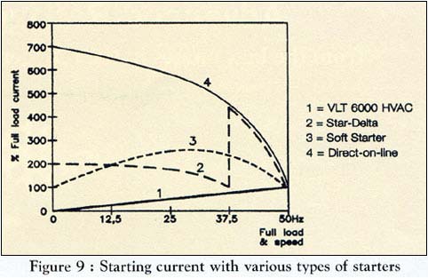
Figure 9, shows the differences in starting currents for various types of frequency inverter systems.
In a retrofit situation existing star/delta starters and power factor correction equipment can be removed reducing energy loss and maintenance related to these components.
Improved Power Factor
An inverter offers a fundamental power factor of near unity at all loads and speeds and hence no Power Factor Correction (PFC) capacitors are required. Added to that is the advantage of substantial restriction on the Reactive Power drawing thus avoiding penalties from the electric supply company.
Removing Unnecessary Energy Loss Caused by Inlet Guide Vanes and Valves
Dampers, guide vanes and valves in fan or pump systems cause a pressure drop across them dependent on the speed of the air or water flow passing through.
When retrofitting with a frequency inverter, dampers, guide vanes or valves can just be left fully open or simply removed. Using a frequency inverter, eliminates these unnecessary pressure drops which improves overall efficiency and capacity.
In constant speed pump systems, bypass loops are commonly used as part of the regulating function keeping constant pressure at varying flow. Bypass systems for pumps can also be eliminated by using a frequency inverter to control the flow of the pump according to the actual need.
Conclusions
The majority of HVAC installations which are operating with constant speed pumps and blowers can be converted into cost efficient (with less drawing of reactive power), energy saving (money saving) installations by investing in inverters and a few transmitters.
Furthermore, the cost reduction for maintenance and replaceable parts is obvious and the improved comfort level will enhance the indoor climate and eventually increase the productivity of people working therein.
All together, a large reduction of the energy bill, often 50% or more, a very short pay back period(typically 1 to 2 years) and increased comfort levels are obtained.
Simple retrofit with frequency inverter is possible with technologically advanced and dedicated HV frequency inverters with matching sensors for a complete system responsibility. Some of the typical applications where substantial energy savings can be achieved are:
These motors are essentially constant speed motors and lack any provisions for speed control when running on main power and are intrinsically unable to adjust to the changing load demands of the application. Therefore suitable external equipment has to be used to control their speed.
Frequency inverter makes it possible to match the speed of the motor to the load or process requirement which also ensures avoidance of losses which may otherwise occur by using other conventional methods.
Again by IEEE estimates 60% - 65% of process needs met by induction motors are for centrifugal fans, pumps and compressors. All these loads are governed by processes, which demand variation of flow and conventional methods to achieve the same are through:
- Dampers
- Throttle Valves
- Inlet Guide Vanes
By using an inverter, a stepless control of motor speed in tune with load requirements encountered by fans or pumps is possible. Retrofitting these frequency inverters onto existing installations can be easily done and therefore a very viable proposition exists of making existing installations of fans and pumps more energy efficient.

The Basics
It is worthwhile for HVAC engineers to understand some basic definitions and issues concerning frequency inverters before applying them on fans and pumps in their system design or in existing installations.
1. Definition – inverter
Inverters are devices used for varying the speed of a driven equipment (such as pumps, blowers, conveyors, extruders, etc) to exactly match the process requirements and achieve energy savings as well, especially for variable torque loads.

2. Frequency inverters
While strictly by definition a "inverter" can be any device which controls the speed of a "driven equipment" the focus of discussion in this article will be restricted to an electronic controller which controls the speed of the induction motor.
A frequency inverter is a device which consists of a frequency converter that can vary the frequency and voltage of the supply fed to the induction motor. The speed of the most commonly used industrial motor, the squirrel cage induction motor, can be varied by varying the frequency of the power supply. frequency inverters facilitate energy savings by variable speed operation, that will be discussed in greater detail later.
3. Concept of Electronic inverters
Any electronic inverter system comprises of the following three components:
- An electronic actuator – the controller
- A driving electrical machine – motor
- A driven machine (load) – pump, fan, blowers, etc.

A frequency inverter consists of an input rectifier (which converts AC to DC) followed by an inverter (that inverts DC to AC) connected through a DC intermediate voltage link. The basic line schematic is shown in Figure 2. For simplicity we are only considering three phase systems though single phase systems are also available within a restricted power range.
Every standard AC motor can be fitted with a frequency inverter for variation of mains supply frequency in line with speed variations required. Both frequency and voltage of single phase or three phase mains are varied by the frequency inverter so as to ensure that the motor can be operated with varying speeds over large range settings.

4. Loading Patterns
All driven equipment has a load characteristic or a speed and torque relationship which can be broadly classified as follows:
- Constant Torque (CT)
- Variable Torque (VT)
- Constant HP or Power
Constant Torque loads are those for which the output power requirement may vary with speed of operation but the torque does not vary. Conveyors, extruders, rotary kilns, positive displacement pumps are typical examples of CT loads.
Variable Torque Load (VT)
Variable Torque loads are those for which the torque required varies with the speed of operation. Centrifugal pumps and fans are typical examples of VT loads (torque varies as the square of speed) Our main topic of discussion will revolve around VT loads only as the largest potential for energy savings exists for this loading pattern in which as the speed is varied the power requirement changes as the cube of the speed.
Constant HP/Power Load
Constant HP / Power loads are those for which torque requirement typically change inversely with speed. Winders and coilers are typical examples of constant power loads.
5. Speed Control of AC Motor
In an AC induction motor due to the tendency of the rotor magnetic field to be aligned with the stator field, the rotor develops the torque in the same direction and it starts rotating. The speed of the rotor however is less than the synchronous speed (NS) – the speed of the rotating magnetic field developed by the stator.
Hence the speed of an AC motor is a function of frequency and the number of motor poles.
The difference between the synchronous speed (Ns) and the actual rotor speed (N) is called the Slip (s). If there is no slip there will be no rotor current and torque, as induced emf into the rotor will be zero.
The speed of an induction motor is directly proportional to the supply frequency. By gradually changing the supply frequency, speed can be increased or decreased continuously and precisely.
If speed control is to be achieved by changing frequency, the supply voltage also has to be changed simultaneously. This is because if frequency (f) is reduced keeping the supplied voltage (V) constant, flux is increased, which causes increase in excitation current and larger losses and thus affects the efficiency of the motor.
On the other hand if the frequency (f) is increased with applied voltage (V) constant, flux will decrease thereby reducing torque.
Therefore it is important that the frequency and voltage should be changed proportionately. The constant V/f ratio of frequency inverters work on this principle.
6. Frequency Inverter Basic Principle of Operation
The electronic frequency inverter can be used to vary the speed of an AC motor and at the same time retain its torque producing capability. The main power source provides a fixed voltage, fixed frequency supply that is converted into a variable voltage, variable frequency output in such a way that in most of the operating speed range, the V/f ratio is maintained constant. This of course is achieved though sophisticated microprocessor based control electronics.
The principle involved in this technique is first to convert the fixed frequency, fixed voltage AC supply into a constant DC voltage through rectification. This DC voltage is then inverted into a variable frequency, variable voltage AC supply at the desired level as determined by the reference level and controlled by the main controller.
It is recommended that a DC reactor be installed at both limbs in the intermediate circuit level for controlling harmonics. See Figure 3.

Applications of frequency inverter in HVAC
In an effort to reduce operating expenses, the one most commonly replaced piece of equipment in an existing central air conditioning plant in an old building, is the packaged chiller (or chillers) either reciprocating or centrifugal, because most operating engineers know that the old chillers, before the energy crisis of the 1970s, were quite inefficient or because of their experience with frequent breakdowns in the past and / or difficulty in obtaining spare parts.
What many engineers do not realize is the potential for very large additional energy savings possible in old buildings by using frequency inverters to reduce the speed of fans in air handling units or the secondary chilled water pumps, in line with the reduction in heat load from morning to evening hours and from season to season as the outdoor temperature varies or as the internal load of equipment and occupants is reduced.
Fans and pumps in such buildings run at full speed all the time, which is wasteful. If control valves are installed in the chilled water lines to each air-conditioning unit or bypass dampers are installed across the cooling coils and controlled through a space thermostat (which is rarely the case in old buildings in India) this method of control of cooling capacity is inefficient and wasteful. Of the total power consumed by a typical office building, a central air conditioning plant alone consumes approximately 60%.
Affinity Laws governing fluid flow
The characteristics of centrifugal equipment such as blowers and pumps versus flow can be explained by the following basic equations:
- Flow is proportional to speed (F α N)
- Pressure is proportional to square of speed (P α N2)
- Therefore Power = F × P α N3
Energy Savings through Speed Control
The power consumption of a blower or pump therefore follows the "Cube Law", which means that by reducing the speed to 80% of the maximum value the power consumption will be reduced to about 50%. As an example, at 80% speed the power consumption is (0.8)3 or 0.512 or 51.2% Variable air systems using constant speed fans with dampers or inlet guide vanes controlling the airflow consume a lot of energy by constantly running the motor at full speed. Similarly in chilled water circuits with both chillers and pumps running at constant speed, energy is wasted by using by-pass loops returning the excess chilled water not required by the plant for the reduced heat load at that point of time. Energy saving of upto 50% or more is often possible in a typical installation after using a frequency inverter. Figure 4 shows the typical power consumption using "valve control" and "frequency inverter" control in a chilled water loop.

The actual savings will of course depend on the variations in cooling load, since on very warm days the air conditioning and ventilation systems will have to run at full speed but such situations occur on very few occasions in a year or may be a couple of hours in a day. The rest of the year or during off-peak periods each day there is scope for energy saving. To more accurately estimate such savings it is necessary to take each chilled water pump and fan system and work out the number of hours the pump or fan has to work at a particular speed (or flow requirement based on the cooling load) during a 24 hour cycle which will help to draw a load or energy consumption profile. Multiplying the number of running hours at various speeds (h) by the associated amount of power (kW) from Table 1 and adding the values will show the total energy consumption (kWh) per year, of the pump or fan motor controlled by the frequency inverter.
Compared to constant speed operation the difference from the above variable speed calculations represents the savings in energy. By repeating this calculation for other pump and fan systems within a building, the total energy saving of the whole building can be worked out.
Figure 5 shows a typical capacity characteristic of a pump as well as the associated motor shaft output in kW Figures may vary a little bit from manufacturer to manufacturer based on the design adopted.
By using an automatic water valve to control flow from AI to BI follow the solid curve in the lower part of Figure 5 to work out the power saving.

By speed regulation it is possible to utilize the pump characteristic and hence power consumption follows the dotted curve from AI to CI.
A theoretical example based on general experience as well as a practical example, will illustrate how power savings can be calculated.
Example 1
A 15kW AHU operating for 12 hours during weekdays and 6 hours during week ends. In total 66 hours per week.
a. Energy cost at constant speed
Energy consumption per week: 15kW × 66h = 990 kWh.
Assume electricity rate is $5.00 per kWh
Energy cost per year: 990 kWh ´× $5.00 × 52 weeks = $2,57,400
b. Energy cost at variable speed
Assume average speed is 75% corresponding to 42% power consumption.
Energy consumption per week: 0.42 × 15kW × 66h = 416 kWh
Energy cost per year: 416 kWh × $5.00 X 52 = $1,08,160
c. Value of energy saved by using "frequency inverter"
$2,57,400 – $1,08,160 = $1,49,240
d. Investment for running a frequency inverter
(approximate figures)
Application engineering
frequency inverter price
Differential pressure transmitter
Installation, commissioning, cabling etc.
=$1,80,000
e. From the above one can see that the payback period is typically 1.20 years.
Notes:
- In this simplistic example we have considered an average of 75% speed throughout which may not always be the case. However the idea is to demonstrate the possibilities of a drastic effect on energy savings with speed variation based on the cubic laws.
- It may be worthwhile to mention that in all probability the ROI (return on investment) will be actually better than what has been calculated because both technology and competitive pressures are contributing to lowering of prices.


Example 2
We can now take a real life example where the building's cooling curve is used to prepare the speed profile of the motor. See Figures 6 and 7.
Based on Figure 6, a block cooling load profile was made giving some expected average fan speed requirement values in percentages using frequency inverter's to meet the cooling load.
From Good Practice Guide issued by the UK Department of Energy, graphs were used to convert the fan speed percentage given in Figure 7 to power consumption percentage, given in Table 1.
Variable Speed Duty
Based on average fan speeds as noted in Figure 7 and the per cent power consumption from Good Practice Guide, the energy consumption in the different periods as well as the total energy consumption (kWh) for variable speed duty can be calculated and summarized as in Table 1.
Table 1 : Summary of energy consumption for variable speed duty based on Figure 7 and 'Good Practise Guide' issued by the U.K. Dept. of Energy
| Period |
Average Fan Speed %age Power |
%age Power |
ActualPower (kW) |
Hours Run(h) |
kWh Used |
|
1 2 3 4 5 6 |
12 50 80 90 78 35 |
5 18 50 70 48 10 |
2 6 17 23 16 4 |
8 3 3 2 3 5 |
16 18 51 46 48 20 |
| Per Day |
|
|
|
24 | 199 |
For the alternative, constant speed duty calculations of the energy consumption were also made.
Constant Speed Duty (Average Values)
To arrive at a reasonable figure of average load for constant speed duty, we assume the following:
- 50% of fan load (16kW for 24 h = 384 kWh i.e. one group of fans constantly running.
- 50% of fan load (16kW) for 12h = 192 kWh i.e. one group of fans running during daytime only. (The above assumption is based on the average fan speed calculated to meet the cooling load profile as shown in Fig. 6)
-
Energy consumed per day = 576 kWh Now we can calculate the energy savings from running variable speed duty as opposed to constant speed duty.
Based on running 365 days a year:
Constant speed duty 365 × 576 = 2,10,240 kWh
Variable speed duty 365 × 199 = 72,625 kWh
Saving = 1,37,615 kWh
This saving works out to 1,37,615 × $5.00 = $6,88,075 per year in monetary terms.
For a typical 45 kW frequency inverter system along with application engineering, pressure sensing mechanism and installation/commissioning an approximate investment of $3,80,000 will be required and based on the above savings the payback period will be 0.55 years.
- In both these examples savings on maintenance has not been considered (though for correct pay back calculations it should be taken into account) as it will depend on the actual situation. Details on payback calculations are given later.
- The second issue is that the payback period will actually be shorter than what has been calculated above.
1. Reduction in mechanical wear and tear
When a HVAC installation no longer runs at full speed additional benefits apart from those related to energy savings are available:
- Increased lifetime of belt drive on fans.
- With soft start/stop there is less wear and tear on bearings.
- Some frequency inverters have automatic belt monitoring, which increases intervals between maintenance
- No more jammed guide vanes/dampers.
- Lower noise levels.
- Longer intervals between air filter changing (lower speed = less dirt)
- On pumps, fitting a frequency inverter will result in eliminating water hammer during start/stop situations.
As a byproduct of the energy savings from reducing fan speeds, acoustic air movement noise from the fan is also reduced.
Noise from fans in a quiet environment can be very annoying. If a fan sized for full occupancy is supplying a partly occupied room, the acoustic noise level can be as high as 70 dbA. The noise level will vary depending on the throttling with dampers or guide vanes. More the throttling, greater is the noise.
Keeping dampers or guide vanes fully open and reducing the speed from 100% to say 50% reduces the noise by 16.5 dbA. (A reduction of 10 dbA corresponds to a 50% reduction in the noise level)
The following formula shows how to calculate the above:
The relationship is graphically shown in Figure 8.
3. Drafts
By reducing the speed of a centrifugal fan the draft from a fan system can be very much reduced. This also increases comfort.
4. Leaks
Leaking water from pump systems, usually caused by water hammer can be totally avoided by using a frequency inverter with zero starting surge. This also extends the life time of pipe work and fittings.
5. Controlling comfort
When using a frequency inverter instead of an inlet guide vane or damper, accurate temperature and pressure control can be maintained as the response time of a frequency inverter to a BMS (building management system) correction signal is very fast and smooth.

Calculations of Payback Time
When calculating energy savings it is important to have the information required to obtain the expected energy savings. And most interesting of all, work out the pay back time of the investment.
Calculation of the pay back time is initially done for each frequency inverter installed and eventually the data for other frequency converters is added. But before anything else it is important to mention that a substantial amount of application engineering must be done to realize the expected energy savings. For example the position of the sensor is very important for obtaining the "cubic savings" which calls for a thorough understanding of the application.
If the sensor is not positioned properly in the duct work not only will "cubic savings" not be obtained but the linear savings actually obtained will be at a lower efficiency and the overall system may not save much, if at all.
Firstly the investment necessary for obtaining energy savings has to be calculated:
- The price of the frequency converter together with the required sensors and the application engineering involved.
- The cost of installing the frequency converter including wiring of power and control cabling as well as the necessary changes in pipe and/or duct work.
Thirdly, the savings on maintenance has to be added to establish the total savings. Eventually the pay back time can be calculated as the total cost of having a frequency inverter installed divided by the total savings (energy and maintenance) for one year.
Pay back time (simple)
Total cost of installing frequency inverter / Total energy savings for one year.
Pay back time(real)
Total cost of installing frequency inverter / Total energy savings per year + savings on maintenance and spare parts.
Government Incentives
Many governments including that of India are actively considering a special depreciation scheme towards investments made in energy saving equipment. CII is actively propagating this concept with the government to encourage control/reduction of energy demands in the country as energy saved means more energy available at a much lower cost. The Singapore government has already implemented tax breaks as well as special depreciation schemes.
Reducing Maximum kW Demand
When using dedicated types of inverters the high starting current of the motors will be avoided as these include a soft starting feature whereby the starting current is restricted to the 100% full load current of the motor. This characteristic reduces the average maximum demand requirement during starting and adds to further savings in the form of avoidance of payment of penalties for overshooting the contractual agreements.

Figure 9, shows the differences in starting currents for various types of frequency inverter systems.
In a retrofit situation existing star/delta starters and power factor correction equipment can be removed reducing energy loss and maintenance related to these components.
Improved Power Factor
An inverter offers a fundamental power factor of near unity at all loads and speeds and hence no Power Factor Correction (PFC) capacitors are required. Added to that is the advantage of substantial restriction on the Reactive Power drawing thus avoiding penalties from the electric supply company.
Removing Unnecessary Energy Loss Caused by Inlet Guide Vanes and Valves
Dampers, guide vanes and valves in fan or pump systems cause a pressure drop across them dependent on the speed of the air or water flow passing through.
When retrofitting with a frequency inverter, dampers, guide vanes or valves can just be left fully open or simply removed. Using a frequency inverter, eliminates these unnecessary pressure drops which improves overall efficiency and capacity.
In constant speed pump systems, bypass loops are commonly used as part of the regulating function keeping constant pressure at varying flow. Bypass systems for pumps can also be eliminated by using a frequency inverter to control the flow of the pump according to the actual need.
Conclusions
The majority of HVAC installations which are operating with constant speed pumps and blowers can be converted into cost efficient (with less drawing of reactive power), energy saving (money saving) installations by investing in inverters and a few transmitters.
Furthermore, the cost reduction for maintenance and replaceable parts is obvious and the improved comfort level will enhance the indoor climate and eventually increase the productivity of people working therein.
All together, a large reduction of the energy bill, often 50% or more, a very short pay back period(typically 1 to 2 years) and increased comfort levels are obtained.
Simple retrofit with frequency inverter is possible with technologically advanced and dedicated HV frequency inverters with matching sensors for a complete system responsibility. Some of the typical applications where substantial energy savings can be achieved are:
- Supply Fans
- Return Fans
- Exhaust Fans
- Smoke Extract Fans
- Stairwell Pressurisation Fans
- Pressure Boosting Fans
- Cooling Tower Fans
- ID Boiler Fans
- Condenser Pumps
- Chilled Water Pumps
Post a Comment:
You may also like:

